Defining a state machine configuration with UI modeling is supported via Eclipse Papyrus framework.
From eclipse wizard create a new Papyrus Model with UML Diagram
Language. In this example it’s named as simple-machine. Then you’ve
given an option to choose various diagram kind’s and a StateMachine
Diagram must be chosen.
We want to create a machine having two states, S1 and S2 where
S1 is initial state. Then event E1 is created to do a transition
from S1 to S2. In papyrus a machine would then look like something
shown below.

Behind a scenes a raw uml file would look like.
<?xml version="1.0" encoding="UTF-8"?>
<uml:Model xmi:version="20131001" xmlns:xmi="http://www.omg.org/spec/XMI/20131001" xmlns:uml="http://www.eclipse.org/uml2/5.0.0/UML" xmi:id="_AMP3IP8fEeW45bORGB4c_A" name="RootElement">
  <packagedElement xmi:type="uml:StateMachine" xmi:id="_AMRFQP8fEeW45bORGB4c_A" name="StateMachine">
    <region xmi:type="uml:Region" xmi:id="_AMRsUP8fEeW45bORGB4c_A" name="Region1">
      <transition xmi:type="uml:Transition" xmi:id="_chgcgP8fEeW45bORGB4c_A" source="_EZrg4P8fEeW45bORGB4c_A" target="_FAvg4P8fEeW45bORGB4c_A">
        <trigger xmi:type="uml:Trigger" xmi:id="_hs5jUP8fEeW45bORGB4c_A" event="_NeH84P8fEeW45bORGB4c_A"/>
      </transition>
      <transition xmi:type="uml:Transition" xmi:id="_egLIoP8fEeW45bORGB4c_A" source="_Fg0IEP8fEeW45bORGB4c_A" target="_EZrg4P8fEeW45bORGB4c_A"/>
      <subvertex xmi:type="uml:State" xmi:id="_EZrg4P8fEeW45bORGB4c_A" name="S1"/>
      <subvertex xmi:type="uml:State" xmi:id="_FAvg4P8fEeW45bORGB4c_A" name="S2"/>
      <subvertex xmi:type="uml:Pseudostate" xmi:id="_Fg0IEP8fEeW45bORGB4c_A"/>
    </region>
  </packagedElement>
  <packagedElement xmi:type="uml:Signal" xmi:id="_L01D0P8fEeW45bORGB4c_A" name="E1"/>
  <packagedElement xmi:type="uml:SignalEvent" xmi:id="_NeH84P8fEeW45bORGB4c_A" name="SignalEventE1" signal="_L01D0P8fEeW45bORGB4c_A"/>
</uml:Model>
After uml file is in place in your project, it can be imported into
configuration using StateMachineModelConfigurer where
StateMachineModelFactory is associated with a model.
UmlStateMachineModelFactory is a special factory which knows how to
process Eclipse Papyrus generated uml structure. Source uml file can
either be given as a Spring Resource or a normal location string.
@Configuration
@EnableStateMachine
public static class Config1 extends StateMachineConfigurerAdapter<String, String> {

    @Override
    public void configure(StateMachineModelConfigurer<String, String> model) throws Exception {
        model
            .withModel()
                .factory(modelFactory());
    }

    @Bean
    public StateMachineModelFactory<String, String> modelFactory() {
        return new UmlStateMachineModelFactory("classpath:org/springframework/statemachine/uml/docs/simple-machine.uml");
    }
}
![[Important]](images/important.png) | Important |
|---|---|
|
As usually Spring StateMachine is working with Guards and Actions which are defined as bean, those need to be hooked into uml by its internal modeling structure. In a below sections you will see how customized bean references are defined within uml definitions. Thought it is also possible to register particular methods manually without defining those as beans. |
![[Tip]](images/tip.png) | Tip |
|---|---|
|
When opening existing uml model defined as uml, you’ll have three
files, |
Uml model is relatively loose what comes for the implementation like Spring StateMachine itself. There are choices what implementation need to take for uml support as it leaves a lot of features and functionalities for an implementation to decide. Below sections go through how Spring StateMachine will implement uml model based on Eclipse Papyrus plugin.
Let’s start by creating an empty state machine model.
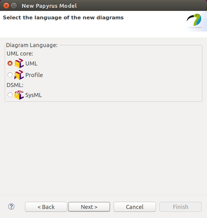
You’ll start by creating a new model and giving it a name.
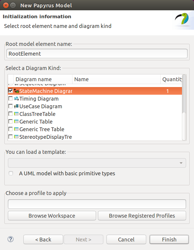
Then you need to choose a StateMachine Diagram.
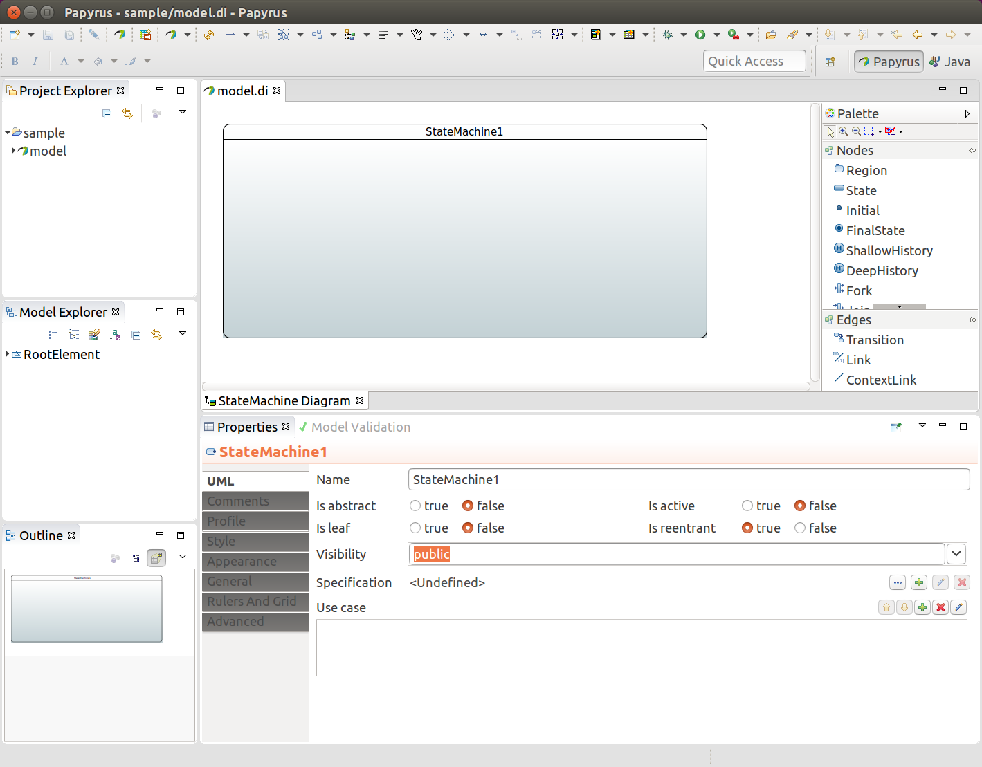
You end up having an empty state machine.
In above sample named model you’ll end up three files, model.di,
model.notation and model.uml which can then be used in any other
eclipse instance and model.uml can be used by importing it into a
Spring Statemachine.
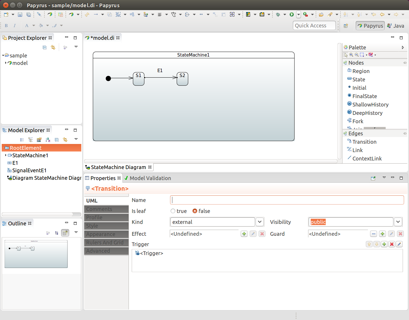
State identifier is simply coming from a component name in a diagram. You must have initial state in your machine which is done by adding Initial and then drawing a transition to your own initial state.
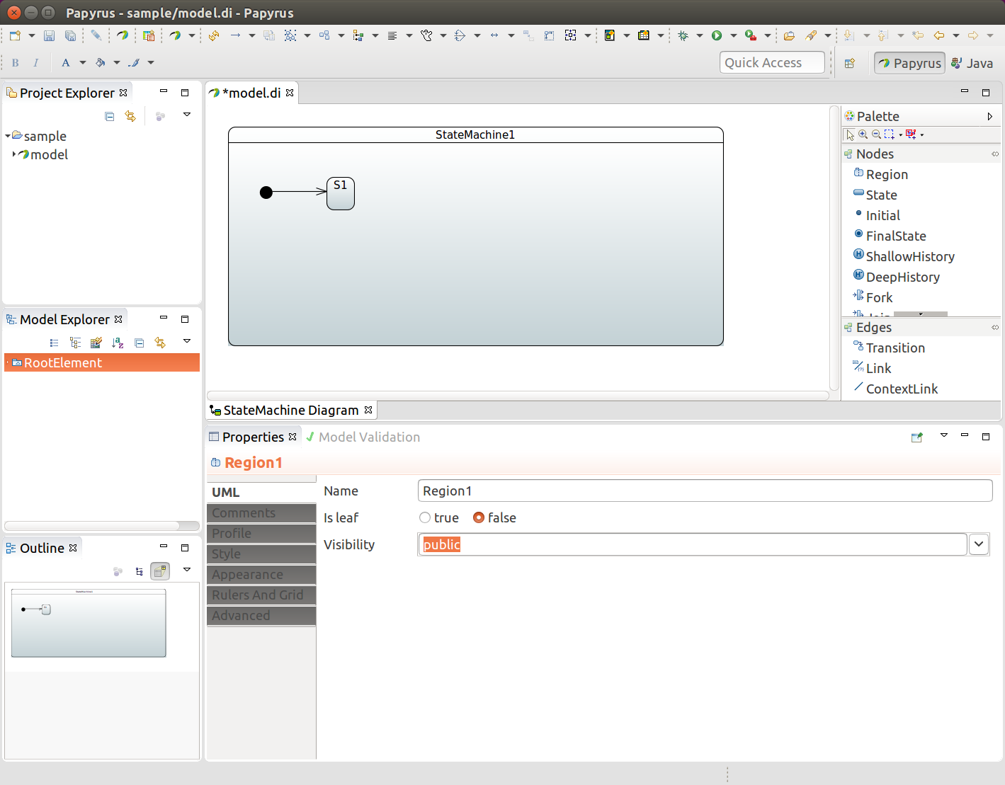
In above we added one state S1, initial state, and draw a transition
between those two to indicate that S1 is an initial state.
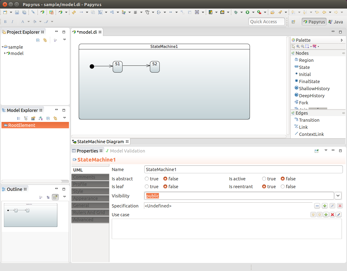
In above we added a second state S2 and added a transition between
those two.
To associate an event for a transition you need to create a Signal
E1. Done from RootElement→New Child→Signal.
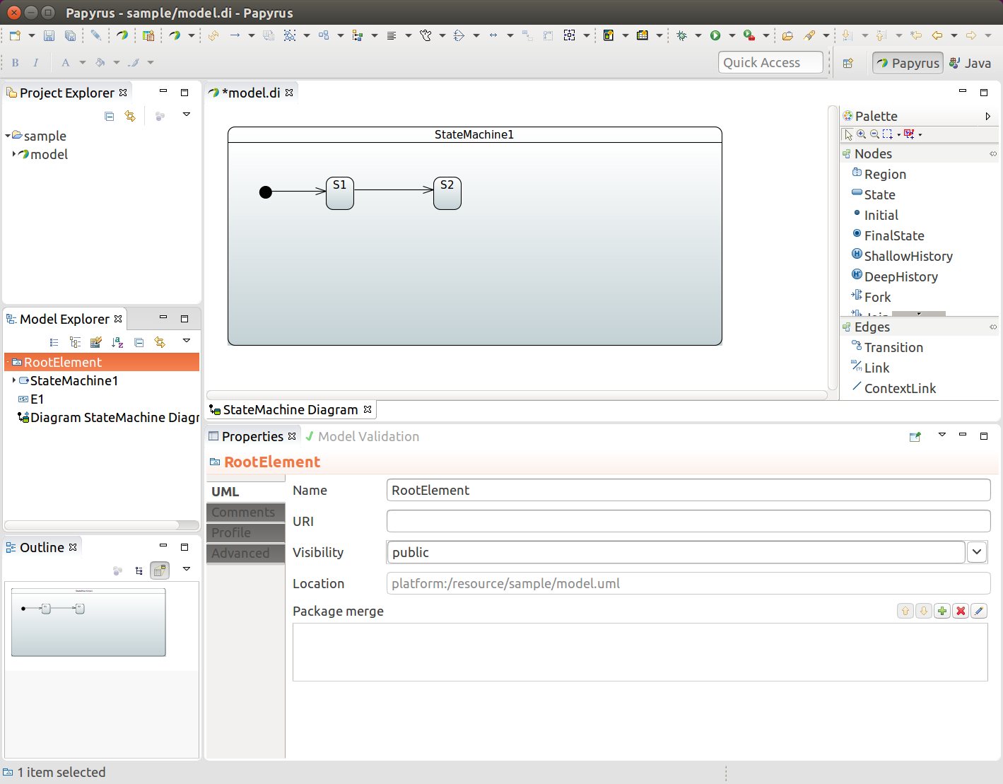
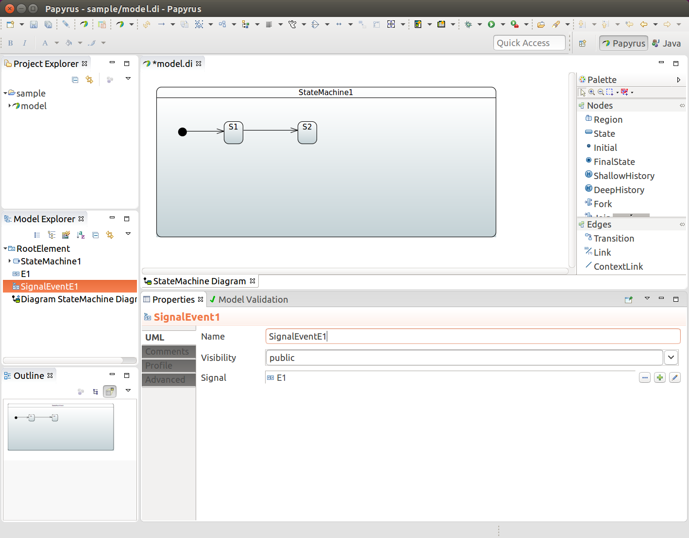
And then SignalEvent with defined signal E1. Done from
RootElement→New Child→SignalEvent.
Transition is simply created by drawing transition line between
source and target states. In above we have states S1 and S2 and
anonymous trasition between those two. We want to associate event
E1 with that transition. We choose a transition, create a new
trigger and define SignalEventE1 for that.
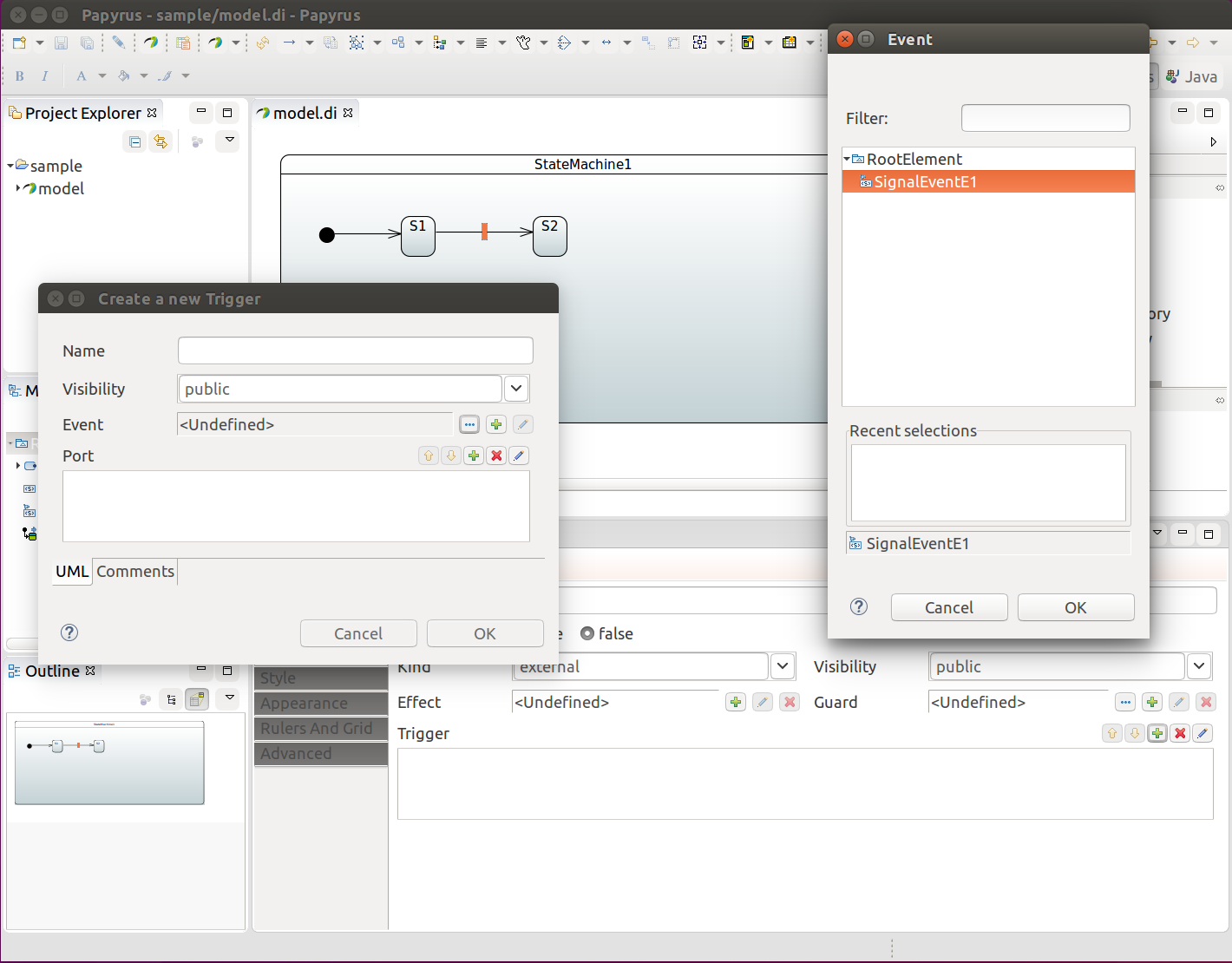
This well give you something like shown below.
![[Important]](images/important.png) | Important |
|---|---|
|
In rest of a sections we skip most of a screenshots as it’s a waste of space. Reference to menu items and actions we do with UI can be found from Model Explorer or other dialogs given by Papyrus plugin. |
State entry and exit actions can be associated by using a behaviour, more about this in Section 27.7, “Define Bean Reference”.
Guard can be defined by first adding Constraint and then defining its Specification as OpaqueExpression which works in a same way than Section 27.7, “Define Bean Reference”.