Defining a state machine configuration with UI modeling is supported via Eclipse Papyrus framework.
From eclipse wizard create a new Papyrus Model with UML Diagram
Language. In this example it’s named as simple-machine. Then you’ve
given an option to choose various diagram kind’s and a StateMachine
Diagram must be chosen.
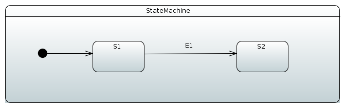
We want to create a machine having two states, S1 and S2 where
S1 is initial state. Then event E1 is created to do a transition
from S1 to S2. In papyrus a machine would then look like something
shown below.
Behind a scenes a raw uml file would look like.
<?xml version="1.0" encoding="UTF-8"?>
<uml:Model xmi:version="20131001" xmlns:xmi="http://www.omg.org/spec/XMI/20131001" xmlns:uml="http://www.eclipse.org/uml2/5.0.0/UML" xmi:id="_AMP3IP8fEeW45bORGB4c_A" name="RootElement">
  <packagedElement xmi:type="uml:StateMachine" xmi:id="_AMRFQP8fEeW45bORGB4c_A" name="StateMachine">
    <region xmi:type="uml:Region" xmi:id="_AMRsUP8fEeW45bORGB4c_A" name="Region1">
      <transition xmi:type="uml:Transition" xmi:id="_chgcgP8fEeW45bORGB4c_A" source="_EZrg4P8fEeW45bORGB4c_A" target="_FAvg4P8fEeW45bORGB4c_A">
        <trigger xmi:type="uml:Trigger" xmi:id="_hs5jUP8fEeW45bORGB4c_A" event="_NeH84P8fEeW45bORGB4c_A"/>
      </transition>
      <transition xmi:type="uml:Transition" xmi:id="_egLIoP8fEeW45bORGB4c_A" source="_Fg0IEP8fEeW45bORGB4c_A" target="_EZrg4P8fEeW45bORGB4c_A"/>
      <subvertex xmi:type="uml:State" xmi:id="_EZrg4P8fEeW45bORGB4c_A" name="S1"/>
      <subvertex xmi:type="uml:State" xmi:id="_FAvg4P8fEeW45bORGB4c_A" name="S2"/>
      <subvertex xmi:type="uml:Pseudostate" xmi:id="_Fg0IEP8fEeW45bORGB4c_A"/>
    </region>
  </packagedElement>
  <packagedElement xmi:type="uml:Signal" xmi:id="_L01D0P8fEeW45bORGB4c_A" name="E1"/>
  <packagedElement xmi:type="uml:SignalEvent" xmi:id="_NeH84P8fEeW45bORGB4c_A" name="SignalEventE1" signal="_L01D0P8fEeW45bORGB4c_A"/>
</uml:Model>
![[Tip]](images/tip.png) | Tip |
|---|---|
|
When opening existing uml model defined as uml, you’ll have three
files, |
After uml file is in place in your project, it can be imported into
configuration using StateMachineModelConfigurer where
StateMachineModelFactory is associated with a model.
UmlStateMachineModelFactory is a special factory which knows how to
process Eclipse Papyrus generated uml structure. Source uml file can
either be given as a Spring Resource or a normal location string.
@Configuration
@EnableStateMachine
public static class Config1 extends StateMachineConfigurerAdapter<String, String> {

    @Override
    public void configure(StateMachineModelConfigurer<String, String> model) throws Exception {
        model
            .withModel()
                .factory(modelFactory());
    }

    @Bean
    public StateMachineModelFactory<String, String> modelFactory() {
        return new UmlStateMachineModelFactory("classpath:org/springframework/statemachine/uml/docs/simple-machine.uml");
    }
}
As usually Spring StateMachine is working with Guards and Actions which are defined as bean, those need to be hooked into uml by its internal modeling structure. In a below sections you will see how customized bean references are defined within uml definitions. Thought it is also possible to register particular methods manually without defining those as beans.
If UmlStateMachineModelFactory is created as a bean its
ResourceLoader is wired automatically to find registered actions and
guards. It’s also possible to manually define a
StateMachineComponentResolver which will then be used to find these
components. Factory also have methods registerAction and
registerGuard which can be used to register these components. More
about this in Section 33.1.1, “StateMachineComponentResolver”.
Uml model is relatively loose what comes for the implementation like Spring StateMachine itself. There are choices what implementation need to take for uml support as it leaves a lot of features and functionalities for an implementation to decide. Below sections go through how Spring StateMachine will implement uml model based on Eclipse Papyrus plugin.
Below example shows how UmlStateMachineModelFactory is defined with
a StateMachineComponentResolver which registers a simple functions
myAction and myGuard respectively. As you notice these components
are not created as beans.
@Configuration
@EnableStateMachine
public static class Config2 extends StateMachineConfigurerAdapter<String, String> {

    @Override
    public void configure(StateMachineModelConfigurer<String, String> model) throws Exception {
        model
            .withModel()
                .factory(modelFactory());
    }

    @Bean
    public StateMachineModelFactory<String, String> modelFactory() {
        UmlStateMachineModelFactory factory = new UmlStateMachineModelFactory(
                "classpath:org/springframework/statemachine/uml/docs/simple-machine.uml");
        factory.setStateMachineComponentResolver(stateMachineComponentResolver());
        return factory;
    }

    @Bean
    public StateMachineComponentResolver<String, String> stateMachineComponentResolver() {
        DefaultStateMachineComponentResolver<String, String> resolver = new DefaultStateMachineComponentResolver<>();
        resolver.registerAction("myAction", myAction());
        resolver.registerGuard("myGuard", myGuard());
        return resolver;
    }

    public Action<String, String> myAction() {
        return new Action<String, String>() {

            @Override
            public void execute(StateContext<String, String> context) {
            }
        };
    }

    public Guard<String, String> myGuard() {
        return new Guard<String, String>() {

            @Override
            public boolean evaluate(StateContext<String, String> context) {
                return false;
            }
        };
    }
}
Let’s start by creating an empty state machine model.
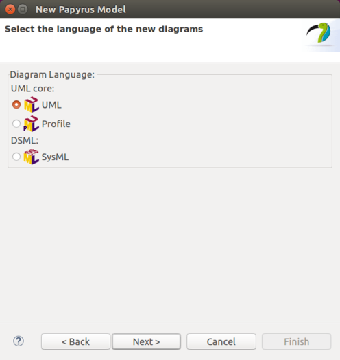
You’ll start by creating a new model and giving it a name.
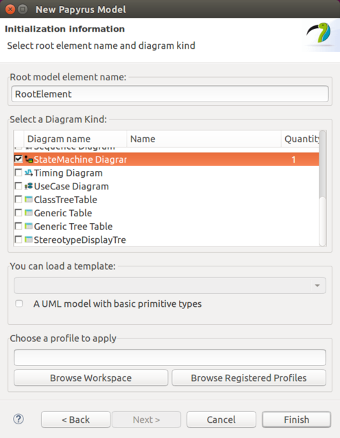
Then you need to choose a StateMachine Diagram.
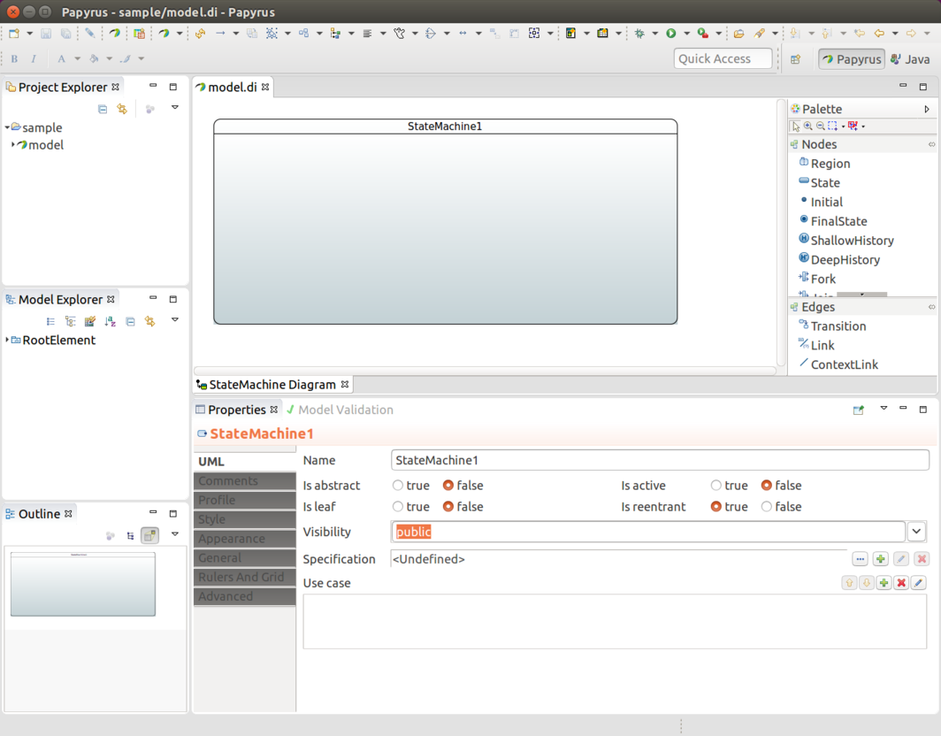
You end up having an empty state machine.
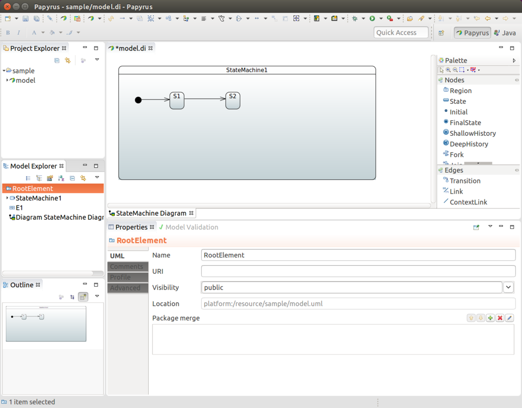
In above sample named model you’ll end up three files, model.di,
model.notation and model.uml which can then be used in any other
eclipse instance and model.uml can be used by importing it into a
Spring Statemachine.
State identifier is simply coming from a component name in a diagram. You must have initial state in your machine which is done by adding Initial and then drawing a transition to your own initial state.
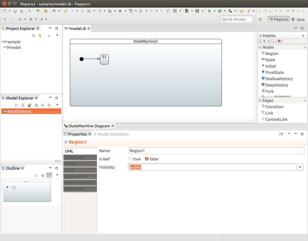
In above we added one state S1, initial state, and draw a transition
between those two to indicate that S1 is an initial state.
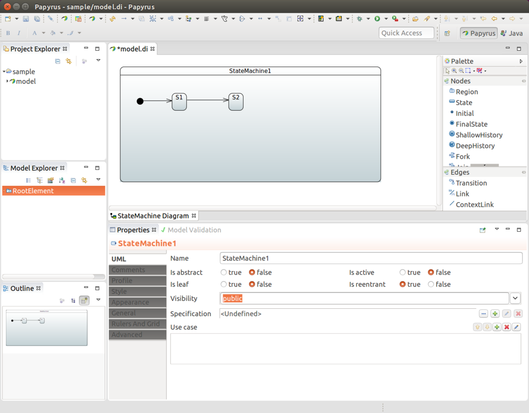
In above we added a second state S2 and added a transition between
those two.
To associate an event for a transition you need to create a Signal
E1. Done from RootElement→New Child→Signal.
And then SignalEvent with defined signal E1. Done from
RootElement→New Child→SignalEvent.
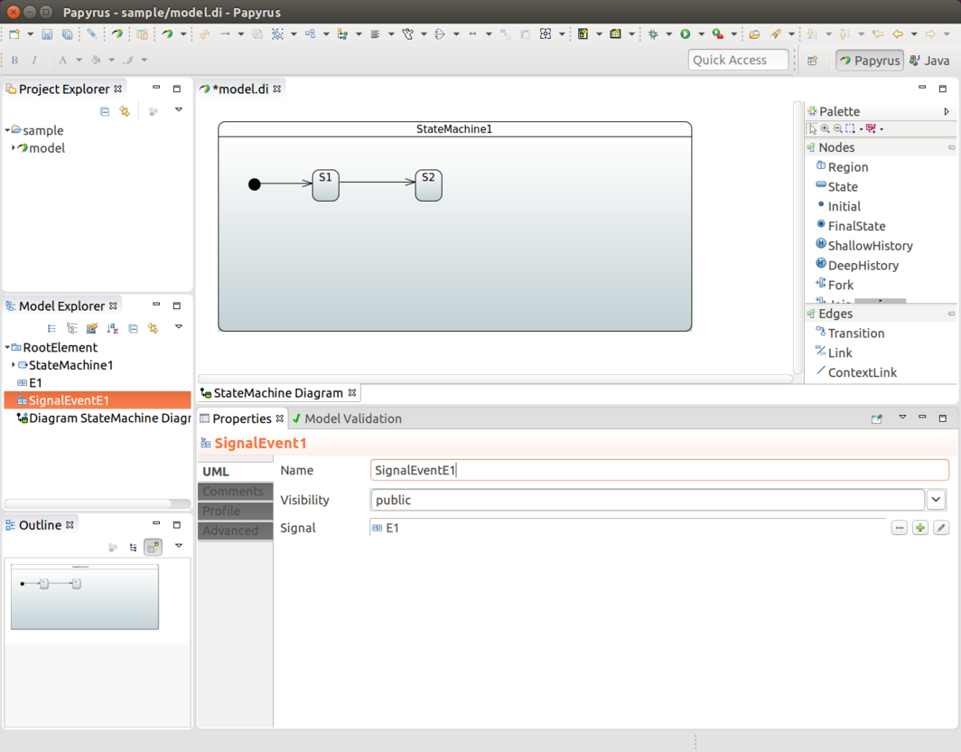
Now that you have a SignalEvent defined it can be used to associate
a trigger with a transition. More about that in
Section 33.5, “Define Transitions”.
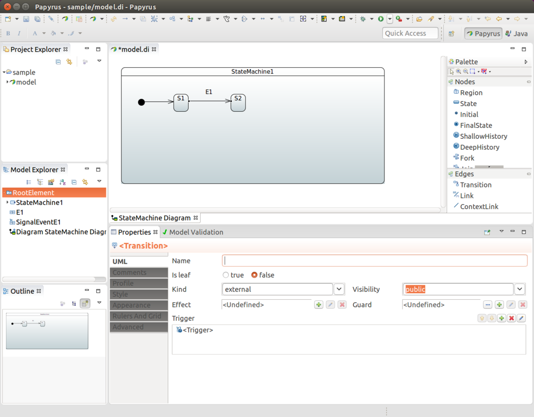
Transition is simply created by drawing transition line between
source and target states. In above we have states S1 and S2 and
anonymous transition between those two. We want to associate event
E1 with that transition. We choose a transition, create a new
trigger and define SignalEventE1 for that.
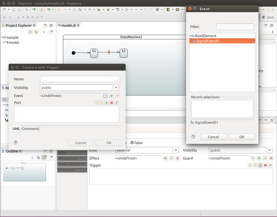
This will give you something like shown below.
| Tip |
|---|---|
|
If |
Transition can also happen based on timed events. Spring Statemachine support two types of timers, ones which fires continuously on a background and ones which fires once with a delay when state is entered.
Add new TimeEvent child to Model Explorer, modify When as
expression defined as LiteralInteger. Value of it is then timer as
milliseconds. Is Relative is left to false making timer to fire
continuously.
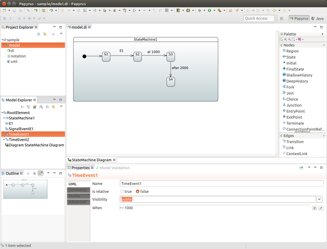
To define one timed based event when state is entered it’s exactly same as above but Is Relative is now defined as true.

Then what is left for user is to pick these time events instead of signal event for a particular transition.
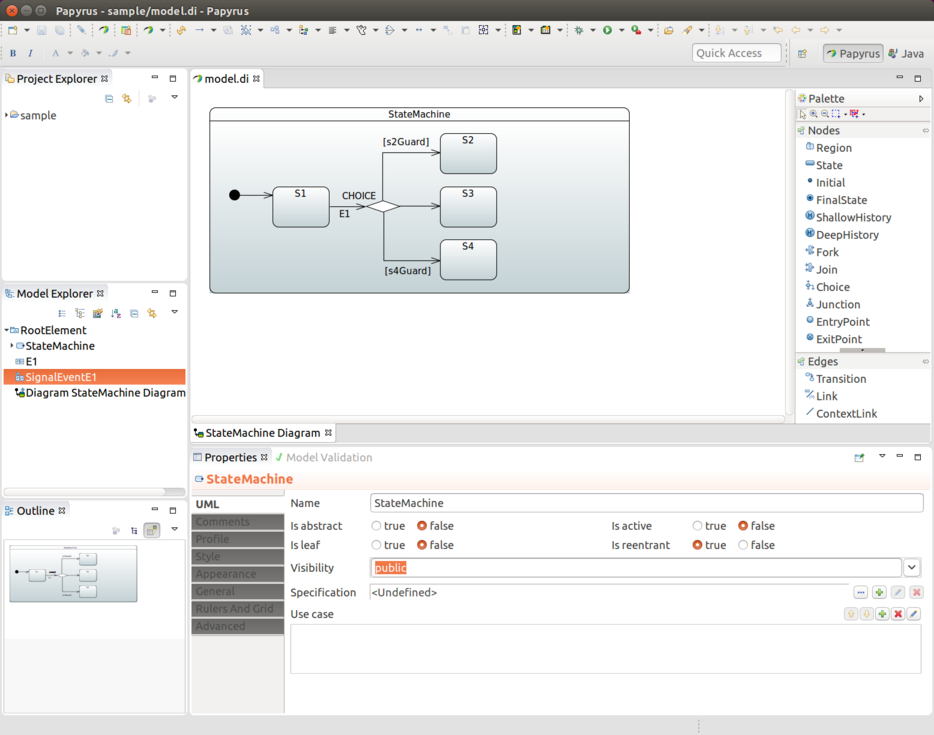
Choice is simply defined by drawing one incoming transition into a
CHOICE states and multiple outgoing transition from it into target
states. Configuration model in our StateConfigurer allows to define
if/elseif/else structure but with uml we simply need to work with
individual Guards for outgoing transitions.
Make sure that guards defined for transitions do not overlap so that whatever happens, only one guard would evaluate to TRUE at any given time. This gives precise and predictable results for choice branch evaluation. Also it is advised to leave one transition without a guard so that at least one transition path is guaranteed.
![[Note]](images/note.png) | Note |
|---|---|
|
Junction is very much same except it allows multiple incoming transitions. Thus its behaviour compared to choice is purely academic. Actual logic to select outgoing transition is exactly same. |
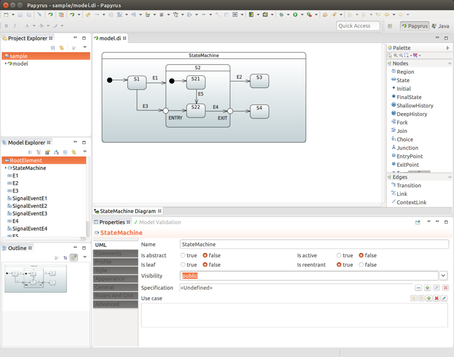
EntryPoint and ExitPoint are used to do controlled entry and exit
with state having sub-states. In a below statechart events E1 and
E2 will do a normal state behaviour by entering and exiting state
S2 where normal state behaviour happens by entering initial state
S21.
Using event E3 takes machine into EntryPoint ENTRY which then
leads into S22 without activating initial state S21 at any time.
Similarly ExitPoint EXIT with event E4 controls specific exit
into state S4 while normal exit behaviour from S2 would take
machine into state S3. While being on a state S22 you can choose
events E4 or E2 to take machine into states S3 or S4
respectively.
| Note |
|---|---|
|
If state is defined as submachine reference and entry/exit points need to be used, a ConnectionPointReference has to be defined externally , its entry/exit reference set to point to a correct entry/exit point within a submachine reference. Only after that it is possible to target a transition which correctly links from outside into inside of a submachine reference. With ConnectionPointReference you may need to find these settings from Properties → Advanced → UML → Entry/Exit. UML Spec allows to define multiple entries and exits but with a state machine only one is allowed. |
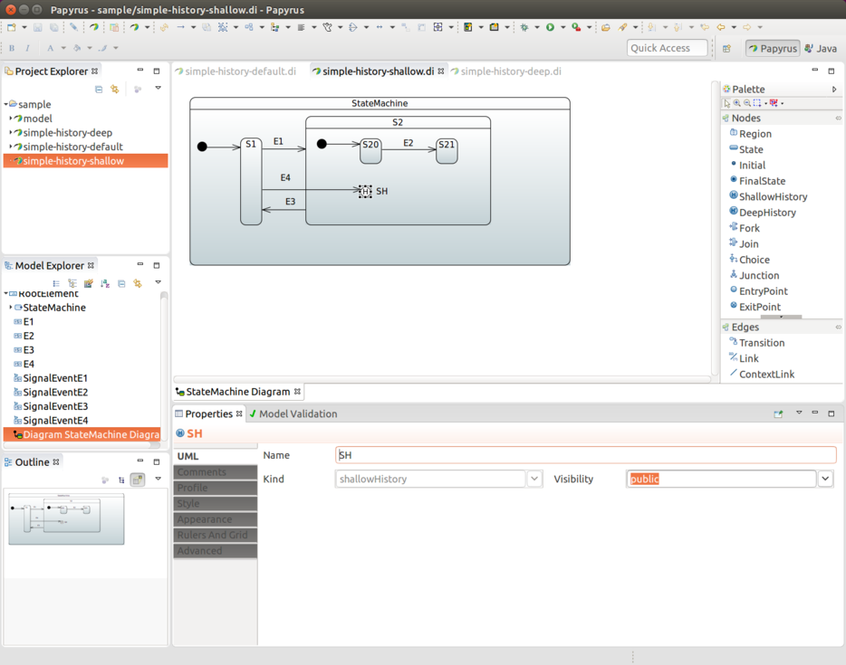
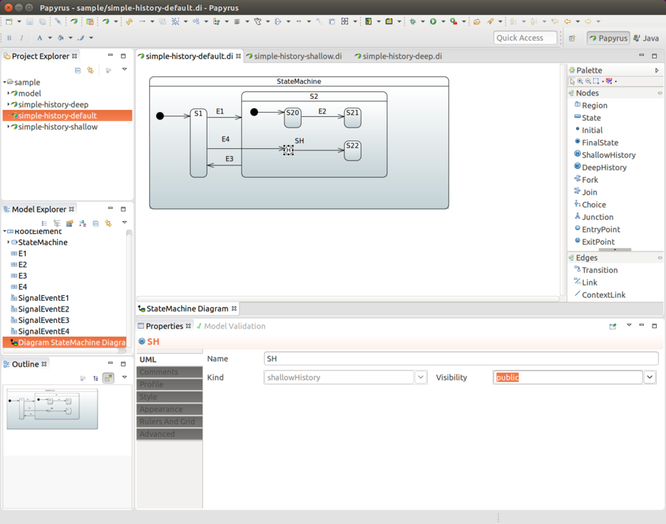
When working with history states three different concepts are in play. UML defines a Deep History and a Shallow History. Default History State comes into play when history state is not yet known. These are represented in following sections.
Deep History is used for state which has other deep nested states, thus giving a chance to save whole nested state structure.
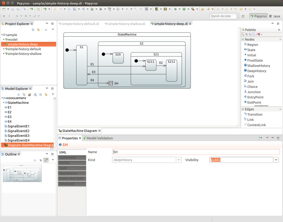
In cases where a Transition terminates on a history when
the state has not been entered before or it had reached its
final state, there is an option to force
a transition to a specific substate, using the default
history mechanism. For this to happen you simply define transition
into this default state. This is would be a transition from SH to
S22.
In a below example state S22 would be entered if state S2 has
never been active as its history has never been recorded. If state
S2 has been active then either S20 or S21 would get chosen.
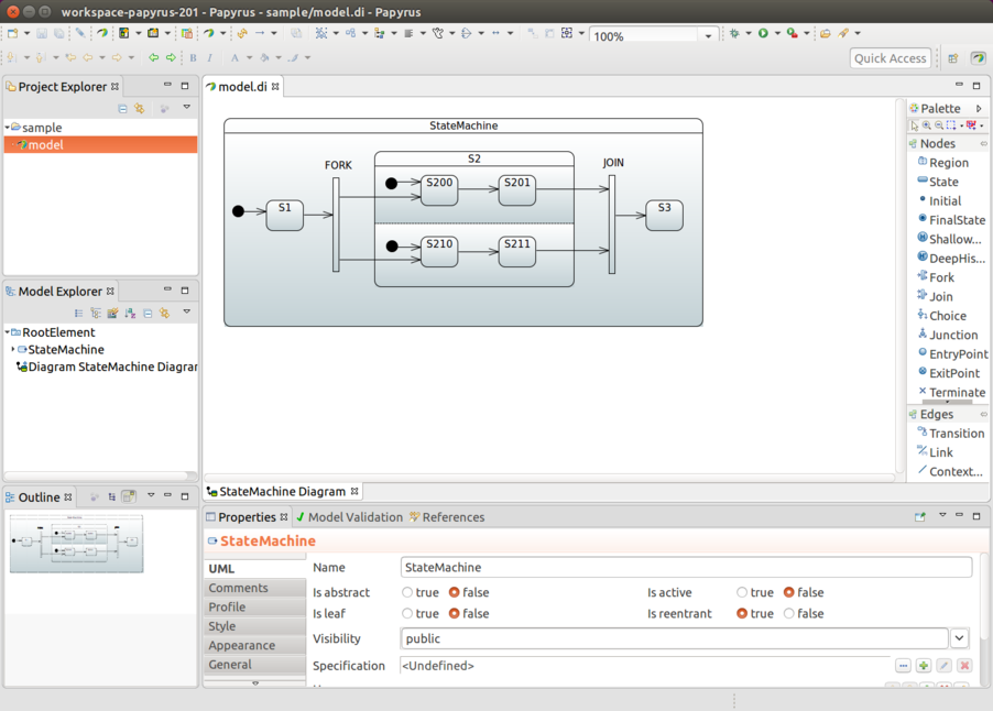
Both Fork and Join are represented as bars in Papyrus. As shown
below you need to draw one outgoing transition from FORK into state
S2 which have orthogonal regions. JOIN is then reverse where
joined states are collected together via incoming transitions.
State entry and exit actions can be associated by using a behaviour, more about this in Section 33.14, “Define Bean Reference”.
Initial action as shown in Section 11.7, “Configuring Actions” is defined in uml by adding action in transition leading from Initial State marker into actual state. This Action is then executed when state machine is started.
Guard can be defined by first adding Constraint and then defining its Specification as OpaqueExpression which works in a same way than Section 33.14, “Define Bean Reference”.
When there is a need to make a bean reference in any uml effect,
action or guard, supported method to do that is via
FunctionBehavior or OpaqueBehavior where defined language needs to
be bean and language body having a bean reference id.
When there is a need to use a SpEL instead of a bean reference in
any uml effect, action or guard, supported method to do that is via
FunctionBehavior or OpaqueBehavior where defined language needs to
be spel and language body having a SpEL expression.
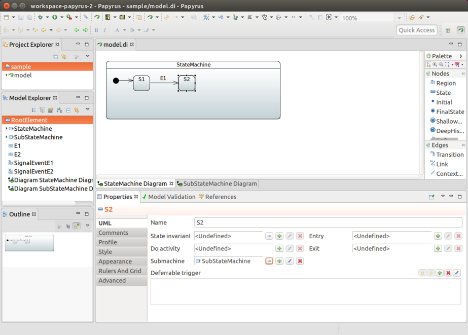
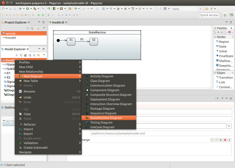
Normally when using sub-states those are simply drawn into a state chart itself. Chart itself may become a little complex and big to follow so we also support defining sub-state as a statemachine reference.
First create a New Diagram and give it a name i.e. SubStateMachine Diagram.
Give new diagram a design you need.
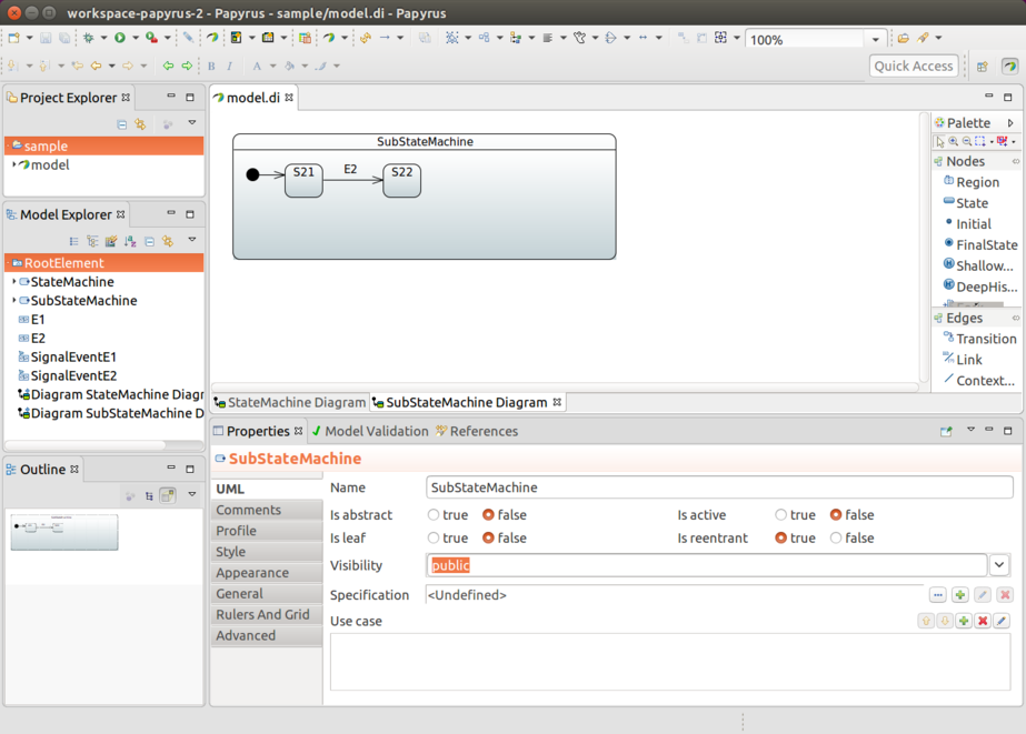
From state you want to link(in this case state S2), click
Submachine field and choose your linked machine, i.e.
SubStateMachine.
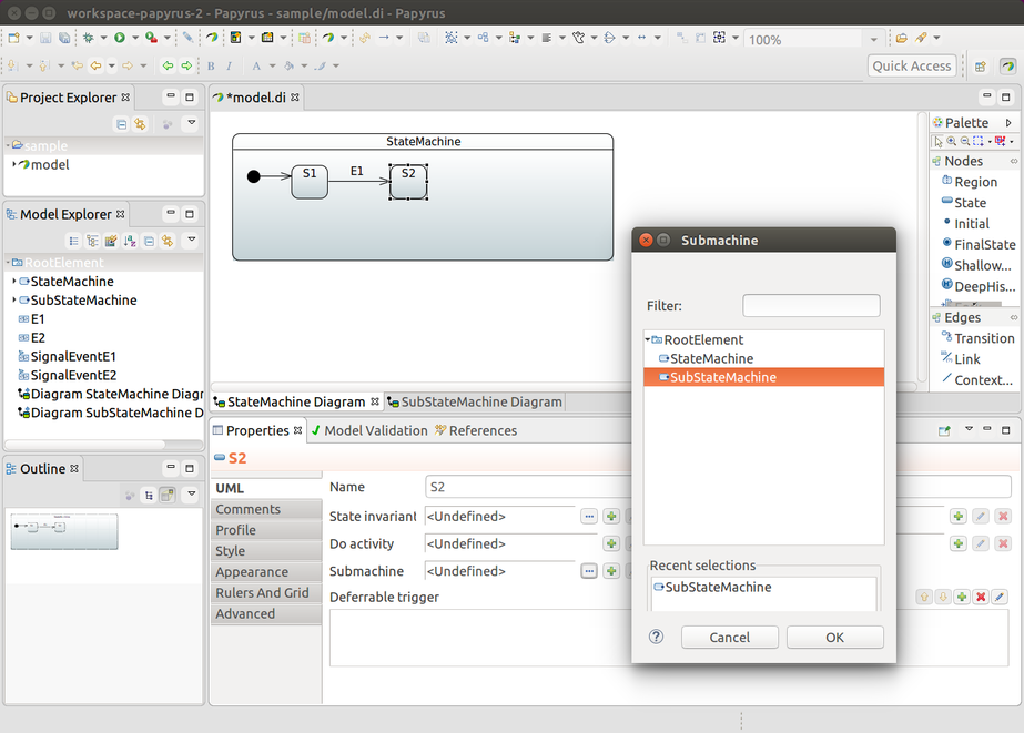
Finally you’ll see that state S2 is linked to SubStateMachine as a
sub-state.